Most basic example of instanced 3d model (using GLB)

I’m relatively new to 3d tiles, so I have some really basic questions. Sorry, if they are too simple and can be easily googled (I also tried it myself, but seems could not find any tips). So, let’s imagine we have some primitive glb model of a tree:
849af735-3acc-4978-a70c-97580db543fa.glb (178.7 KB)

What we want is to put this model, say, in three different geographic positions. What is the right way to do this and how some simple tileset.json can look like? Can I use my glb model or should this instancing be hardcoded inside gltf first, and then packed in glb model?

And some relative question is about EXT_mesh_gpu_instancing. Khronos readme about this extension is rather short and not so informative. So, am I right to say that this extension is just some optimization, that can be applied to glb/gltf and improve rendering/visualization? Should I apply this extension only to those models, that can have multiple instances (like trees) or should I use it even for sigle models (like some unique building)?

And one more question is about LODs. What if I have multiple LODs of a model (same model, but with simpler geometry for each level). For example, I have three LODs of my tree model. What is the best practice to combine multiple instances with LODs? Should I create separate layers of some instanced model, referencing different LODs? Or probably we can use just one single layerset? It would be great to have some simple example. Thanks in advance!

The two questions are fairly unrelated, and for both, there are several options of how to address them. The “best” solution usually involves several engineering questions and a clear idea about the intended application patterns. But I’ll try to give a short summary:

What we want is to put this model, say, in three different geographic positions. What is the right way to do this and how some simple tileset.json can look like? Can I use my glb model or should this instancing be hardcoded inside gltf first, and then packed in glb model?

And some relative question is about EXT_mesh_gpu_instancing. Khronos readme about this extension is rather short and not so informative. So, am I right to say that this extension is just some optimization, that can be applied to glb/gltf and improve rendering/visualization?

Indeed, the main options are:

  1. refer to this GLB file, multiple times, from a tileset JSON file
  2. create the instances in a single GLB, with EXT_mesh_gpu_instancing

The advantage of option 1. might be that it is a bit easier and more flexible. For example, you could change the position of one of the trees without having to create the GLB file and its EXT_mesh_gpu_instancing data. You could also more easily show/hide a single tree, or select it by clicking on it. (This is also possible with EXT_mesh_gpu_instancing, but with much more effort)

The advantage of option 2. is mainly/only performance. With EXT_mesh_gpu_instancing, you could easily and efficiently render 100000 trees. In contrast to that, having a tileset JSON that contains 100000 tiles that should all be rendered will be slow.

So when you only want to put it in three (or “few”) positions, then the easiest solution might be to just reference that model from a tileset.json, from three different tiles, where each tile has a different transform matrix.

For the given tile, such a tileset JSON (for two trees) could look like this:

{
  "geometricError": 1000.0,
  "root": {
    "geometricError": 1000.0,
    "refine": "ADD",
    "boundingVolume": {
      "box": [
        1254723.2027332075, -4733011.404296879, 4073472.2598072663,
        11.931891988846473, 0, 0, 0, 18.70224343938753, 0, 0, 0,
        18.34575758059509
      ]
    },
    "children": [
      {
        "geometricError": 900.0,
        "transform": [
          0.9666108723721498, 0.2562487490934376, 0, 0, -0.1645317843574858,
          0.620639953066638, 0.7666389897426187, 0, 0.1964502821278028,
          -0.7410415826696163, 0.64207839039047, 0, 1254719.4320267234,
          -4733000.450009609, 4073473.670362134, 1
        ],
        "boundingVolume": {
          "box": [
            0.8377834740791688, 0.38224225730407735, 7.952663400546863,
            7.760191485177515, 0, 0, 0, -7.9996707314338495, 0, 0, 0,
            8.4149664158071
          ]
        },
        "content": {
          "uri": "849af735-3acc-4978-a70c-97580db543fa.glb"
        }
      },
      {
        "geometricError": 900.0,
        "transform": [
          0.9666108723721498, 0.2562487490934376, 0, 0, -0.164531235764166,
          0.6206378836857364, 0.7666407827607444, 0, 0.1964507415864546,
          -0.7410433158204309, 0.6420762495280394, 0, 1254722.3549911848,
          -4733011.475894566, 4073460.0507147997, 1
        ],
        "boundingVolume": {
          "box": [
            0.8377834740791688, 0.38224225730407735, 7.952663400546863,
            7.760191485177515, 0, 0, 0, -7.9996707314338495, 0, 0, 0,
            8.4149664158071
          ]
        },
        "content": {
          "uri": "849af735-3acc-4978-a70c-97580db543fa.glb"
        }
      }
    ]
  },
  "asset": {
    "version": "1.1"
  }
}

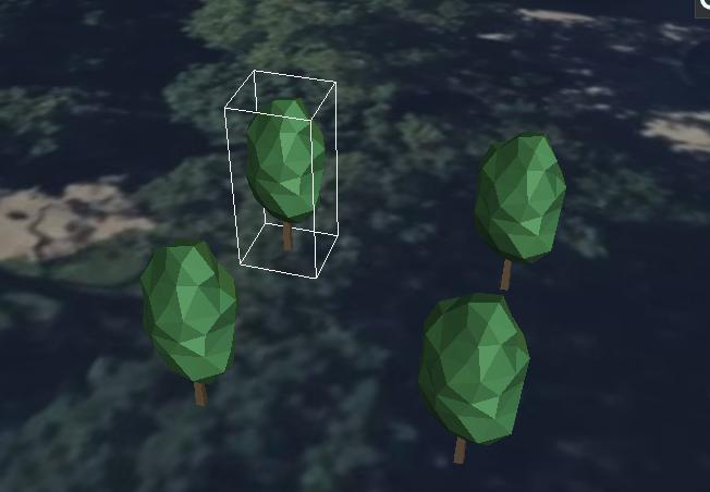
And when this is rendered, it will look like this

Should I apply this extension only to those models, that can have multiple instances (like trees) or should I use it even for sigle models (like some unique building)?

As I said above: This extension is intended for the case where you have many instances of the same model. An example where a user has used this extension to create many trees can be found at From I3dm to EXT_mesh_gpu_instancing? - #10 by bertt (the link at the bottom now should point to https://bertt.github.io/cesium_3dtiles_samples/samples/1.1/trees/ )


What is the best practice to combine multiple instances with LODs?

This mainly depends on which of the approaches you are going to use. A basic example of a tileset with LODs can be found at https://github.com/CesiumGS/3d-tiles-samples/tree/main/1.0/TilesetWithDiscreteLOD, and you could use that when you refer to the instances directly from the tileset JSON (i.e. with option 1.).

For option 2.,when using EXT_mesh_gpu_instancing: In the most simple case, you could just create three separate GLB files, which contain the same EXT_mesh_gpu_instancing information, and use this to instantiate different models. But one might have to put more thought into that, and whether it really makes sense, depending on the exact model and use-case.

about EXT_mesh_gpu_instancing: It seems to work a little bit different compared to i3dm, did you manage to create a sample that places a tree correctly on the ground @Marco13 ?

@bertt There are some different approaches for “placing something” - e.g. via glTF node transforms, via instancing transforms, or via tile transforms. But I’ll attach an example that contains

  • a tree.glb
  • a small CreateInstancedTrees.ts script, based on glTF-Transform, that reads that tree.glb and creates a treeInstanced.glb
  • the resulting treeInstanced.glb
  • a tileset JSON that was created by running createTilesetJson command of the 3d-tiles-tools on this file, and where I manually inserted a transform for the root tile to place that tile at a certain position on the globe

The result looks right …

Cesium Simple Trees Instanced

(Yes, the bounding box is wrong: The bounding box computation does not take the instancing into account, see Support for skinning and instancing in getBounds() · Issue #879 · donmccurdy/glTF-Transform · GitHub )

27549b.zip (140.4 KB)

Which are the differences compared to I3DM that you refer to?

1 Like

Ok, thanks I inspected the example, I see the first tree is placed roughly in the center of the park (lon/lat -75.152645,39.946864), when trying to put the second tree on the park north/east crossing Walnut/South 6 (-75.151097,39.947724) so about 173 meter to the east/125 meter to the north it’s not placed correctly :frowning:

I’ve used as offsets:

const translations = [
0.0, 0.0, 0.0,
173, 0, -125,
];

I supposed +x : east +y: up +z: south

What would be the correct procedure to place the second tree at a known coordinate? Maybe eastNorthUpToFixedFrame should be involved

Ohhh … OK, that’s something else, and indeed something that could be emphasized when trying to convert between I3DM and GLB+Instancing. It is a somewhat low level aspect, but might be important for people who want to create such data.

In an I3DM, the translations are indeed given in meters. When there is a GLB that is contained in an I3DM, and the I3DM defines translations like (1,0,0) and (2,0,0), then the distance between the instances should be 1 meter.

However, in the GLB+Instancing case, the instancing extension is not applied to the whole glTF, but only to the mesh that is contained in a node. This means that the "TRANSLATION" that is put into the instancing extension will still be affected by the transform of the node. For the given tree.glb, the node that contains the mesh is

  "nodes" : [
    {
      "name" : "tree-beech",
      "matrix" : [
        0.43513906,
        0.0,
        0.0,
        0.0,
        0.0,
        0.43513906,
        0.0,
        0.0,
        0.0,
        0.0,
        0.43513906,
        0.0,
        -13.904818,
        0.1899376,
        17.165821,
        1.0
      ],
      "mesh" : 0
    }
  ],

which contains some scaling and translation components. This means that the translations that I used in the CreateInstancedTrees.ts, which are

  const translations = [
    0.0, 0.0, 0.0, 
    10.0, 0.0, 0.0, 
    0.0, 0.0, 10.0, 
    10.0, 0.0, 10.0, 
  ];

will eventually translate the trees by 10 * 0.43513906 meters along the axes.

(Admittedly, I just threw some random numbers into this array, without thinking about the exact units…)

If the "TRANSLATION" in the instancing extension should really be meters, then this would require the (global) transform of that node to be the identity matrix.

Fortunately, glTF-Transform offers some helpful functionality here: The clearNodeTransform and clearNodeParent functions will allow you to easily “bake” any transforms into the meshes. Depending on the exact layout/structure of the input GLB, one might want to update the translation before baking it,so that the object is centered on top of the origin, by calling the center transform to the model before “baking” it.

I updated the code snippet and the resulting GLB here:

27549c.zip (140.6 KB)

And the result will be instances that should indeed be 10 meters apart:

Cesium Trees Baked


EDIT:

eastNorthUpToFixedFrame should be involved

this should, very roughly speaking, only be necessary for translations that are large enough to be affected by the curvature of the earth. At this point, the question of what the translations (and rotations!) should be, exactly, will become more difficult (but equally so for the I3DM and the GLB case…)

1 Like

tried it again with the 27549c script, but this time the second tree (supposed to be at the crossing) is too far :slight_smile: vector is alright though…

demo: https://bertt.github.io/cesium_issues/instanced_gpu_trees/27549c/

I’ve used for translations:

const translations = [
0.0, 0.0, 0.0,
135, 0, -120,
];

so 135 m to east, 120 m to north from the center of the parc. Might be missing something else in the script? Or the translations should be calculated differently?

The transform of the root node of the tileset should be the one that is created with

const transform = Cesium.Transforms.eastNorthUpToFixedFrame(
  Cesium.Cartesian3.fromDegrees(-75.152408, 39.946975, 0)
);
console.log(Cesium.Matrix4.toArray(transform));

(which is not perfectly in the center of the park, but … I just tweaked these coordinates as needed for some of the samples, and just used them here as well…)

Putting these coordinates into Google Maps and measuring the horizontal and vertical distance to the crossing yields slightly different numbers for me:

Cesium Instancing Distance

Using a translation of (110, 0, 83) for the second instance should yield a result like this:

The original tree is visible in the lower left. The other tree appears to be exactly at the center of the crossing.

EDIT: How did you measure the values (135 and -120)? In doubt, I’ll go through that again, and see whether I modified the lat/long or the transform matrix at some point, but from this quick test, it seemed to be correct…

measured it in QGIS/PostGIS (180 meter diagonal), quite a difference compared to Google Maps (140 meter diagonal).

Got it working now by using different distance formula :slight_smile: see https://bertt.github.io/trees/lyon/1.1/

Got the impression the ‘baking’ of the tree model doesn’t have impact on the position. Anyway, thanks for your assistance :slight_smile:

1 Like

@bertt Bert, can you, please, share what distance formula you used? I’m doing almost the same at the moment

@bertt And how do you get trees’ coordinates? From some machine learning pipeline?

I’ve used this distance formula https://github.com/charlesRollandy/GeoCoordinate.NetStandard2/blob/master/src/GeoCoordinate.NetStandard2/GeoCoordinate.cs#L282

For tree data I use https://opentrees.org/

1 Like

Thank you, Bert!

1 Like

Got the impression the ‘baking’ of the tree model doesn’t have impact on the position.

From the first comparison, it did seem to have an impact: When the root node contained the scaling factors, a translation of 10.0 caused the trees to be nearly touching each other ( post 5 ), but when the model was “baked”, they had a larger distance ( post 7 ).

In general, the root node could contain “anything” (e.g. rotations as well), so “baking” it should make it more likely to have the desired result. There still are caveats, though. If you’re curious, the PR Upgrade I3DM to GLB with `EXT_mesh_gpu_instancing` by javagl · Pull Request #52 · CesiumGS/3d-tiles-tools · GitHub tracks some of the issues here. I originally tried to be “clever”, but … I’m not :slight_smile: so I eventually settled with an approach that also involves ‘baking’…

From a quick look, this formula does involve a magic number (and websearching for 6376500.0 brings exactly the expected results), and it does not seem to take into account that the earth is an ellipsoid. It should be possible to compute these distances with plain Cesium, though. I’d imagine something like

  • create cartographics for (lon0, lat0) and (lon0, lat1)
  • convert to cartesians
  • compute distance - this is the distance in X-direction
  • do the same for (lon1, lat0) and (lon1, lat1) to compute the distance in Y-direction

but that would have to be reviewed/verified. If the linked formula gives the desired result with sufficient precision, then that’s fine.

theory: the formula for distances I used before (giving the larger distances with QGIS/PostGIS) is using the ellipsoid, but for the instancing to work we need to have distance calculated without it (like in Google Maps)?

There are some guesses involved on my side, and before I’d make a (confident) statement here, I’d go though the numbers and do some tests. But I’m surprised (and cannot explain) the difference between the measurement from your QGIS screenshot to that in Google maps.

In Google maps, it’s 140m (direct connection).
Bing Maps agrees with that - it’s also 140m there.
In QGIS, it’s 181 … what?
It says ‘map units’. I wondered whether this might be one of these obscure non-metric units. But even if it was ‘yards’, it would be ~165m, so still way off. (140 * ‘50 inch’ = 177.8 meters is close - maybe one ‘map unit’ is ‘50 inches’? :laughing: )

the formula for distances I used before (giving the larger distances with QGIS/PostGIS) is using the ellipsoid,

The screenshot says that it is using the cartesian distance, which sounds like what I suggested: Convert each cartographic point into a cartesian, and then compute their (euclidean) distance).

In any case: The distances are small, but the differences between the distances are large (compared to the distances themself). So I’m reasonably sure that this cannot be attributed to the ellipsoid or even the difference between the direct- and the surface-distance.

yeah I’m also surprised by the difference.

Calculation in PostGIS for the 2 diagonal points gives also 180 (it goes to spherical mercator 3857 first, so result is in meters):

SELECT ST_Distance(
ST_Transform(‘SRID=4326;POINT(-75.152408 39.946975 0)’::geometry, 3857),
ST_Transform(‘SRID=4326;POINT(-75.1511072856895 39.947722248035234 0)’::geometry, 3857) );

Using the formula (https://github.com/charlesRollandy/GeoCoordinate.NetStandard2/blob/master/src/GeoCoordinate.NetStandard2/GeoCoordinate.cs#L282) I get 138 meter (like google maps) - this distance gives good results for instanced glb’s

Update: when using st_distancespheroid in PostGIS 138.7087793627962 meter is returned

SELECT st_distancespheroid(ST_Point(-75.152408,39.946975 ),st_point(-75.1511072856895,39.947722248035234));

1 Like