I have a tough problem. First of all, I am really excited to receive your reply. I have found a solution to the problem I asked you half a month ago, but I found some new problems in the process of using Cesium to conduct research. I will discuss them in detail below. Warning: the article is long and messy.
My research direction is Discrete Global Grid Systems, so I used Cesium to draw DQG, a subdivision method proposed by my postgraduate tutor, as shown in the following picture: so beautiful!
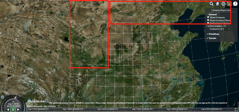
But as I narrowed the distance, the problem arose, camera position:Cartesian3.fromDegrees(109, 35,5000000):
If you zoom in a little more, the problem becomes obvious, camera position:Cartesian3.fromDegrees(109, 35, 3000000):
I found out why: the OrientedBoundingBox of these undrawn grids don’t intersect with the six planes of Camera.frustum. But
these boxes are already in the Camera.frustum and why the intersection is -1,means that outside. as shown in the following figure:
The green are the six planes of Camera.frustum. The red is the OrientedBoundingBox of undrawn grids. We’ve seen the red OrintedBoundingBox in the frustum, why the intersection is -1??? The code:
tile.boundingBox = OrientedBoundingBox.fromRectangle(tile.rectangle, 0.0, 0.0);
var cullingVolume = camera.frustum.computeCullingVolume(camera.positionWC, camera.directionWC, camera.upWC);
var intersection = cullingVolume.computeVisibility(tile.boundingBox);
the result of intersection is -1.
Finally I found the reason: boundingVolume.intersectPlane was miscalculated.
boundingVolume.intersectPlane in CullingVolume.prototype.cumputeVisibility in CullingVolume.js. The code:
var result = boundingVolume.intersectPlane(Plane.fromCartesian4(planes[k], scratchPlane));
After struggling for days, I finally found the culprit:
Cartesian3.fromCartesian4(coefficients, scratchNormal)
In Plane.fromCartesian4().The Plane.fromCartesian4() source code:
Plane.fromCartesian4 = function(coefficients, result) {
var normal = Cartesian3.fromCartesian4(coefficients, scratchNormal);
var distance = coefficients.w;
if (!CesiumMath.equalsEpsilon(Cartesian3.magnitude(normal), 1.0, CesiumMath.EPSILON6)) {
    throw new DeveloperError('normal must be normalized.');
}
    if (!defined(result)) {
        return new Plane(normal, distance);
    }
    Cartesian3.clone(normal, result.normal);
    result.distance = distance;
    return result;
};
The Cartesian3.fromCartesian4() source code:
Cartesian3.fromCartesian4 = Cartesian3.clone;
Cartesian3.prototype.clone = function(result) {
return Cartesian3.clone(this, result);
};
Cartesian3.clone = function(cartesian, result) {
if (!defined(cartesian)) {
return undefined;
}
if (!defined(result)) {
return new Cartesian3(cartesian.x, cartesian.y, cartesian.z);
}
result.x = cartesian.x;
result.y = cartesian.y;
result.z = cartesian.z;

return result;
};
So I added a little code to test Cartesian3.fromCartesian4()’s problems: print coefficients and normal. And their x y z should be the same.
var count = 0;
Plane.fromCartesian4 = function(coefficients, result) {
*//>>includeStart(‘debug’, pragmas.debug);
- Check.typeOf.object(‘coefficients’, coefficients);
*//>>includeEnd(‘debug’);
// test code begin:
- var normal = Cartesian3.fromCartesian4(coefficients, scratchNormal);*
- var distance = coefficients.w;
console.log(“coefficients:”);
console.log(coefficients);
console.log(“normal:”);
console.log(normal);*
//>>includeStart(‘debug’, pragmas.debug);
- if (!CesiumMath.equalsEpsilon(Cartesian3.magnitude(normal), 1.0, CesiumMath.EPSILON6)) {
throw new DeveloperError(‘normal must be normalized.’);
}
*//>>includeEnd(‘debug’);
- if (!defined(result)) {
return new Plane(normal, distance);
}
Cartesian3.clone(normal, result.normal);
result.distance = distance;
return result;
};
But their do not have the same x y z. When the screen pixels are 1920x903 :
when the screen pixels are 1280x833 :
The four children QuadTree grid of red rectangle mean that their father gird is intersect or inside with the camera.frustum.
normal = Cartesian3.fromCartesian4(cofficients, result) , I want to know the reason why normal.x != cofficients.x normal.y != cofficients.y
and normal.z != cofficients.z. (However I found that although normal != cofficients, the value of normal is not random. So I think that there must be rules in Cesium)
Please forgive me for disturbing you and my poooooooor English.
Looking forward to your reply.
Zhang Yaoyuan