Polyline's location is not fixed while rotating globe

1. A concise explanation of the problem you’re experiencing.

I drew 3 axes X, Y, Z by using Cesium.Polyline and used cartesian (0, 0, 0) as origin. Each length of axis is 1,000 Km, so they will be expected to be partially above ground.

To distinguish the undergound part and part above ground, I set the depthFailMaterial attributes for polyline (underground parts will be a little bit transparent).

The problem is: I noticed that the juction point of undergound part and part above ground is not fixed at a specific location, it will be moved when I rotate the globe (or tilt the camera).

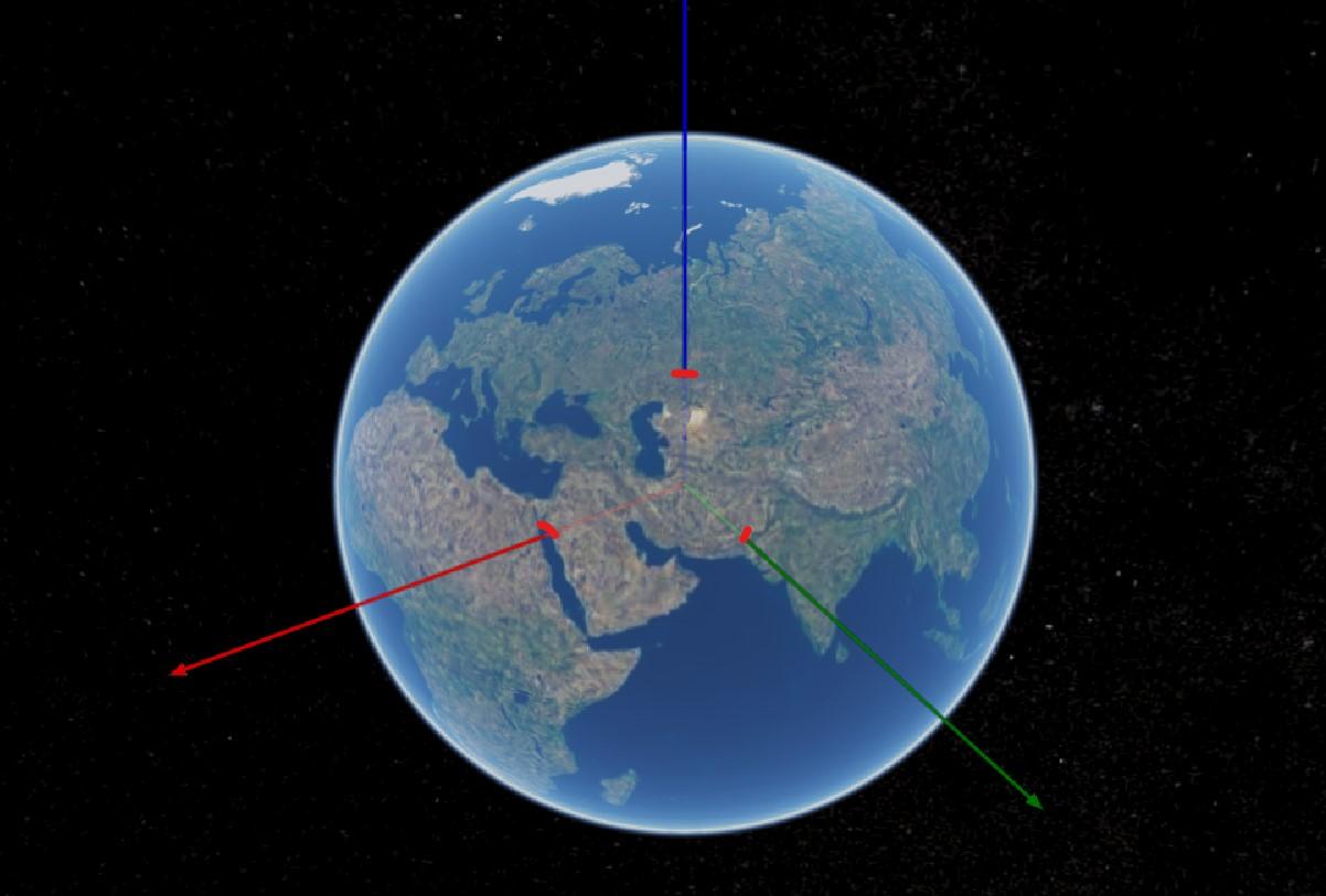
(the junction point)

Demo link: http://203.66.57.234/axis/

2. A minimal code example. If you’ve found a bug, this helps us reproduce and repair it.

let xAxis = viewer.entities.add({

name : ‘X axis’,

polyline : {

positions : [new Cesium.Cartesian3(0.000001, 0, 0), new Cesium.Cartesian3(10000000(6371000), 0, 0)],

width : 10,

arcType : Cesium.ArcType.NONE,

material : new Cesium.PolylineArrowMaterialProperty(Cesium.Color.RED),

depthFailMaterial: new Cesium.PolylineArrowMaterialProperty(new Cesium.Color(1.0, 0, 0, 0.2))

}

});

let yAxis = viewer.entities.add({

name : ‘Y axis’,

polyline : {

positions : [new Cesium.Cartesian3(0, 0.000001, 0), new Cesium.Cartesian3(0, 10000000, 0)],

width : 10,

arcType : Cesium.ArcType.NONE,

material : new Cesium.PolylineArrowMaterialProperty(Cesium.Color.GREEN),

depthFailMaterial: new Cesium.PolylineArrowMaterialProperty(new Cesium.Color(0, 1, 0, 0.2))

}

});

let zAxis = viewer.entities.add({

name : ‘Z axis’,

polyline : {

positions : [new Cesium.Cartesian3(0, 0, 0.000001), new Cesium.Cartesian3(0, 0, 10000000)],

width : 10,

arcType : Cesium.ArcType.NONE,

material : new Cesium.PolylineArrowMaterialProperty(Cesium.Color.BLUE),

depthFailMaterial: new Cesium.PolylineArrowMaterialProperty(new Cesium.Color(0, 0, 1, 0.2))

}

});

3. Context. Why do you need to do this? We might know a better way to accomplish your goal.

I want to draw XYZ axes to indicate 3D models’ origin.

4. The Cesium version you’re using, your operating system and browser.

Cesium v1.58 on Windows Chrome browser (76.0.3809.100)

No solution, but a little easier to see the problem with points drawn at the surface of the ellipsoid at the expected “exit” points.

var viewer = new Cesium.Viewer(‘cesiumContainer’);

var xAxis = viewer.entities.add({

name : 'X axis',

polyline : {

    positions : [new Cesium.Cartesian3(0.000001, 0, 0), new Cesium.Cartesian3(10000000, 0, 0)],

    width : 10,

    arcType : Cesium.ArcType.NONE,

    material : new Cesium.PolylineArrowMaterialProperty(Cesium.Color.RED),

    depthFailMaterial: new Cesium.PolylineArrowMaterialProperty(new Cesium.Color(1.0, 0, 0, 0.2))

}

});

var xSurface = viewer.entities.add({

name : 'X axis surface',

position: Cesium.Cartesian3.fromDegrees(0.0, 0.0),

point: {

    color: Cesium.Color.DODGERBLUE,

    pixelSize: 7,

    outlineColor: Cesium.Color.WHITE,

    outlineWidth: 2

}

});

var yAxis = viewer.entities.add({

name : 'Y axis',

polyline : {

    positions : [new Cesium.Cartesian3(0, 0.000001, 0), new Cesium.Cartesian3(0, 10000000, 0)],

    width : 10,

    arcType : Cesium.ArcType.NONE,

    material : new Cesium.PolylineArrowMaterialProperty(Cesium.Color.GREEN),

    depthFailMaterial: new Cesium.PolylineArrowMaterialProperty(new Cesium.Color(0, 1, 0, 0.2))

}

});

var ySurface = viewer.entities.add({

name : 'Y axis surface',

position: Cesium.Cartesian3.fromDegrees(90.0, 0.0),

point: {

    color: Cesium.Color.DODGERBLUE,

    pixelSize: 7,

    outlineColor: Cesium.Color.WHITE,

    outlineWidth: 2

}

});

var zAxis = viewer.entities.add({

name : 'Z axis',

polyline : {

    positions : [new Cesium.Cartesian3(0, 0, 0.000001), new Cesium.Cartesian3(0, 0, 10000000)],

    width : 10,

    arcType : Cesium.ArcType.NONE,

    material : new Cesium.PolylineArrowMaterialProperty(Cesium.Color.BLUE),

    depthFailMaterial: new Cesium.PolylineArrowMaterialProperty(new Cesium.Color(0, 0, 1, 0.2))

}

});

var zSurface = viewer.entities.add({

name : 'Z axis surface',

position: Cesium.Cartesian3.fromDegrees(90.0, 90.0),

point: {

    color: Cesium.Color.DODGERBLUE,

    pixelSize: 7,

    outlineColor: Cesium.Color.WHITE,

    outlineWidth: 2

}

});

``

Not quite a solution either, but the problem seems to go away if you turn on terrain. Perhaps a potential workaround?

Hello Omar, thanks for your reply.

Actually I’ve set Cesium World Terrain for another test case, the junction points would still move around while rotating globe :frowning:

Omar Shehata於 2019年8月21日星期三 UTC+8上午4時53分59秒寫道:

Can you share this test case? It would be great to get a Sandcastle example (https://cesiumjs.org/Cesium/Apps/Sandcastle/index.html), you can click “Share” at the top and paste the sharable link here.

Hello Omar, Here’s the example: link

I add a checkbox to switch the terrain between Cesium World Terrain and default Ellipsoid Terrain.

Omar Shehata於 2019年8月21日星期三 UTC+8下午9時05分42秒寫道:

Sorry, the solution of adding Cesium World Terrain only seems to work when logarithmic depth buffer is turned off.

Try this example link.