Rendering Custom primitives

Hey,

I’m trying to use Cesium’s rendering stack to render custom primitives.

See : https://codepaste.net/3fahb3

I have a series of Cartesian-coordinates to use as data for the mesh.

Along with that I also have a series of indices that must be connected to triangulate the mesh.

I have created a new primitive that implements an update method.

The sequence f actions I am following is.

createBuffers -

  • Create Vertex buffers for the data.

  • Create an index buffer to render the points as a series of triangles.

  • Create a vertex array baed on the bound buffers.
    createShaderProgram -

  • Create shader sources based on vertex and fragment shader texts.

  • Create shader program from the sources.
    createDrawCommad -

  • Create a new draw command and set the vertex array and shader program props.

  • Add the draw command to the frame states command list.
    When I add this primitive to the scene I get an error saying Fragment shader failed to compile.: " ‘v’ syntax error " on line 0.

The frament shader is very basic as follows.

######### meshFSShader.glsl ###########

void main() {

gl_FragColor = vec4(1.0,0.0,1.0,1.0);

}

It seems to be throwing a compilation error for the ‘v’ in void main.

Could anyone point out what I’m doing wrong.

Regards,

Sushrut Shivaswamy

I have managed to get my primitive to render now.

However I’m seeing a lot of rendering artifacts.

There seems to be some kind of depth fighting going on.

The primitive is visible only when I move the camera.

Also the visibility seems to rely on the Render Pass I set in the draw command.

I see the primitive partially only when the pass is set to OVERLAY.

In the Scene/Pass.js it as stated that OVERLAY pass is not sorted based on multiple view frustrums.

Do I need to set an appropriate Bounding Sphere for my primitive as currently I have just assigned a

Bounding sphere with its default constructor with no centre and radius?

Could anyone help me figure out how to set the Draw Command and render state properties appropriately.

A few things I noticed…

drawCommand.count should either be set to the correct count or stay undefined. Also your suspicion about the bounding sphere is correct, it needs to be specified correctly for proper view frustum culling and near/far plane determination in most of the passes.

Your vertex shader is a little unusual. The positions seem to be defined in world space so I’m pretty sure you want to use czm_modelViewProjection instead of czm_viewportOrthographic.

Let me know if that helps, also screenshots are always helpful.

Never mind about the screenshot - I see it now, it was hidden for me.

You’re right Sean. I forgot to update the shader. I am now using the ModelView Projection matrix but even with that I see some sort of depth fighting.
I have set BoundingSphere appropriately by computing it from the set of points I have.

The primitive still shows only in the OverLay pass where there is no View Frustrum as stated in Pass.js(what does that mean?).

In the draw call in Context.js the count seems to be teken from the length of the index buffer but I’ll try leaving it undefined.

Sorry, Imeant there is no sorting based on multiple View Frustrums.
Pass.js

"// Commands are executed in order by pass up to the translucent pass.

// Translucent geometry needs special handling (sorting/OIT). The compute pass

// is executed first and the overlay pass is executed last. Both are not sorted

// by frustum."

In Context.js the count only comes from indexBuffer.numberOfIndices if drawCommand.count is undefined, so keeping it undefined is definitely best.

The overall view frustum is split into multiple sub-frustums with different near/far values. In the opaque pass objects are grouped into the correct frustum based on their bounding spheres. In the opaque pass there is no sorting among the objects in the sub-frustum.

You could try setting drawCommand.cull to false just to make sure it isn’t getting culled in the opaque pass.

I know you left a comment in your code, but using higher precision positions will help reduce artifacts, I’m not sure if that’s what you mean by depth fighting.

Do you have updated code or a closer up screenshot?

Thanks for the reply Sean.
I have managed to get my custom primitive rendering.

I update my code to start using Encoded Cartesian3’s for the precision issues.

I also set the DrawCommand.count to null.

I had two seperate position vectors in my vertex shader corresponding to high precision and low precision bits.

Initially I tried this approach.

attribute vec3 positionWaterMeshHigh;

attribute vec3 positionWaterMeshLow;

void main() {

vec4 positionInEyeCoords = czm_translateRelativeToEye(positionWaterMeshHigh, positionWaterMeshLow);

gl_Position = czm_projection*positionInEyeCoords;

}

I assumed that czm_tranlateRelative to eye gives the combined Cartesian position in EyeSpace so there is no need to multiple by the View Matrix.

This didn’t work.

To overcome this I did the following:

attribute vec3 positionWaterMeshHigh;

attribute vec3 positionWaterMeshLow;

void main() {

vec4 combinedPosistion = vec4(positionWaterMeshHigh + positionWaterMeshLow, 1.0);

gl_Position = czm_projectionczm_view3DcombinedPosistion;

}

I avoided the use of the czm_translateRelativeToeye function and just combined the high and low precision parts by adding them.

I then converted the coords to clip-space by multiplying the combinedCoords by the View matrix and Projection matrix.

This worked. I am now able to see my mesh drawn properly.

What exactly does the czm_translateRelativeToeye function do?

Good to hear that’s working now.

The main difference between adding the components vs. using czm_translateRelativeToEye is czm_translateRelativeToEye will produce a final position that is relative to the camera’s position, rather than purely world space (and not eye space either). This produces more accurate results than world-space positions as the range is typically much smaller. By the way to get it to work you also need to use czm_modelViewProjectionRelativeToEye.

I’m staring to face some kind of precision issues.
I’m creating a simple uniform grid for my mesh and creating an index buffer to render

the mesh as a series of triangles. (GL_TRIANGLES)

When I create a grid of 100 by 100 points I get the expected output.

However, when I up the grid count to show 1000 by 1000 point mesh the values start getting stacked.

Here is the image with both meshes next to each other.

As you can see the upper half of the high resolution mesh fails to render properly.

Could this be an issue with floating point numbers in JavaScript.

Also I notice in PolylineCollection.js a new vertexBuffer is created when the size of the buffer goes beyond 64k.

Seeing as with a 1000*1000 grid the buffer size would go beyond 64k could this be the issue?

Is there a reason new buffers are created beyond 64k indices.

Yeah, when the number of vertices exceeds 65536 then UNSIGNED_SHORT is no longer sufficient for the index buffer. You will need to use IndexDatatype.UNSIGNED_INT, which is technically a WebGL extension (https://www.khronos.org/registry/webgl/extensions/OES_element_index_uint/) but it has pretty wide support. Otherwise you will have to split up your vertices into separate buffers like PolylineCollection.

Hey Sean,

Thanks to you I have made quite a lot of progress in rendering my own mesh.

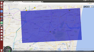
I have manged to render a rectangular mesh and apply the water material on it.

Then by using another image as an alpha map I am able to discard certain fragments.

See the attached images.

While creating the mesh I am supplying DEM data as a texture so that I can look

up the texture in the vertex shader and carry out vertex displacement so that my mesh

conforms to the surface of the globe where the same DEM data has been applied as terrain.

This works but is very inefficient as DEM data can be very large in size and I don’t see why I need to resend data

that is already part of the globe.

I have been looking into Cesiums implementation of ground primitives using Shadow Volumes and other approaches such as Ray Casting

to make the mesh conform to the surface of the terrain.

Shadow volumes is not usable as I require my mesh to have actual geometry as In I should be able to see the mesh and Terrain as separate

entities and provide a certain offset between mesh and terrain.

Ray casting to render fragments I just don’t understand.

Is there any way I can drape my mesh on the surface of the globe without explicitly offsetting each vertex based on the DEM data?

This sounds like a pretty hard problem. Raycasting in screen space is definitely doable as long as you can get the screen’s depth texture, but I’m not sure how performant it will be. The approach outlined here seems promising: http://casual-effects.blogspot.com/2014/08/screen-space-ray-tracing.html

I also bet you could hack something together based on shadow volumes but I really haven’t thought it through at all.