Hello!
I completed the Terrain Modification Web App and I want to introduce my results to the Cesium community.
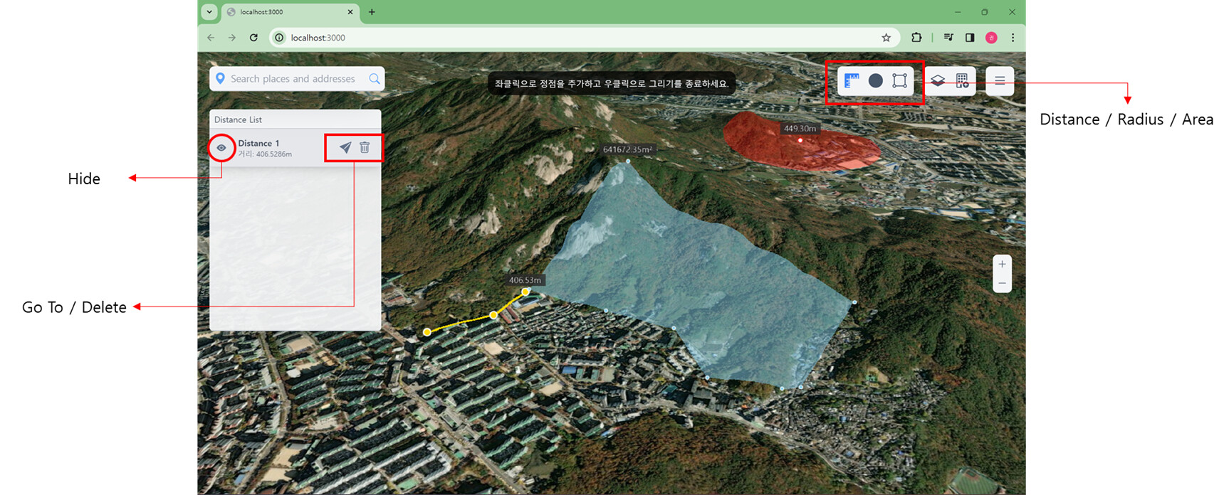
The first feature is measurement, which is a default feature in GIS web applications.
The difference is that I created a data list on the left side of the viewer and resolved the kinked polygon problem in Cesium.
Hi,
I read your post about adding entities to the viewer. Please can you help me I’m trying to add a 3d model to my Cesium App but I noticed the models were not showing in the app, I wouldn’t mind if you could help me with any suggestion on how to go about it.
Your model might be added below ground level and not visible.
Adjust the height value or check in the network tab to confirm if the model is being loaded.
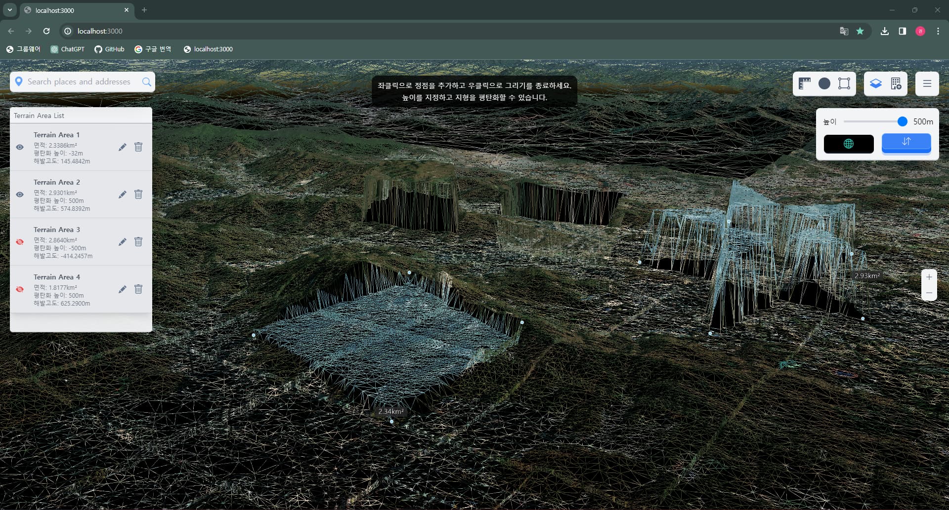
The terrain flattening tool is achieved by adjusting the height of terrain vertices, but it becomes ineffective when there are no vertices in the drawn area. Is there a good solution?
The more detailed the DEM information, the smaller the area that can be flattened.
There is no way in frontend, it only depends on terrain information in backend.
This is why I introduced wire view mode to check the areas that can be flattened.
Cesium currently lacks a terrain modification API, so I referred to another open-source code. Due to uncertainty about sharing someone else’s code, I will provide my modified code instead.
As a side note, it is presumed that the open sourcecode I referred to originated from that forum.
Cesium’s built-in ClippingPlaneCollection can only achieve single convex polygon removal. Due to functional requirements, I need to implement concave polygon removal or multiple polygon removal. The following is a forum post, but he needs to modify the Cesium source code, so I don’t think it’s a perfect solution.
To my knowledge, the cesium clipping plane creates an infinite plane with only the normal vector and distance, and this plane cannot be modified.
If you don’t want the concave polygon part to be rendered for one tile,
consider creating multiple clipping planes vertically, as in the example below.
Hi goni000211,
How you solved z values of point you added. When I click a position and add a point on this location it have been drawn under building or glb models How can I solve it.
Here is my code