I’m working with a 3DTiles BIM dataset in Cesium and currently I can only retrieve each model’s center point. I’d like to:
Obtain the bounding box coordinates of a specific floor (or any component) within my BIM tileset.
Or, ideally, access the full geometry (vertex positions) for that floor so I can work with its exact shape.
For example, in the Cesium Sandcastle I can get the object and change its color, but I need the actual extents (or per-vertex data) to perform more precise operations.
Is there a built-in API or recommended approach to:
Read a tile’s boundingVolume.box, convert it to world coordinates, and compute its eight corner positions?
Drill into the glTF content of a loaded tile to access that floor’s POSITION attribute (vertex buffer)?
Any sample code or pointers to relevant Cesium classes/events would be greatly appreciated!
Unfortunately I don’t have a great path forward for you, but here’s what you might be able to do:
Whether or not you can obtain the bounding box of a component of your tileset will depend on how your tileset is structured. If each tile is a model (a Model3DTileContent), then you might be able to access its original bounding volume (likely a bounding box…) from its internal members. But if each element of the tileset composes multiple model components, there’s no way to access individual bounding boxes.
As for accessing vertex data directly, this is not currently possible. Doing so would mean needing to read back data from GPU buffers, and somehow interpreting it in whatever its original form was. If this is important, consider making a feature request for it. I’ve seen similar questions before, so you’re not the only one who wants to be able to do this.
I do need this feature and hope the Cesium team can implement it, because it’s important for my current project. For example, I need to select an individual office in the BIM. Previously we created a separate simplified “white” model for selection/highlight, which produced a very good solid highlight effect. To avoid the extra loading of that white model, we later tried splitting the office floor directly in the BIM to achieve selection, but that does not reproduce the same solid/highlighted-volume effect.
Is it possible to achieve that same solid highlight without using a separate white model? Or do we still have to obtain the floor’s vertex data from the BIM to make it work?
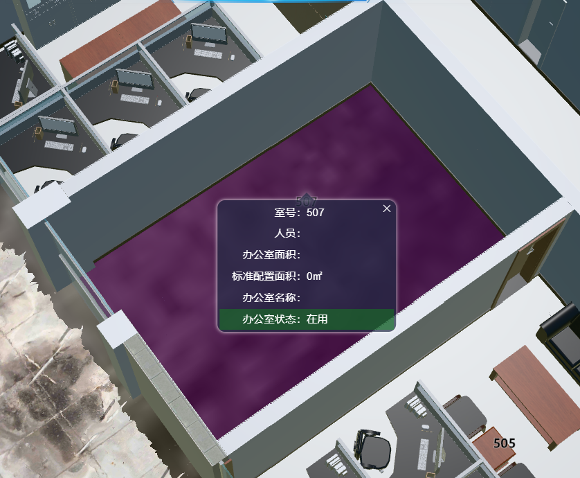
See the images below: the first image shows the effect using the separate white model; the second image shows the result of highlighting the BIM directly.
I’m not sure I see what you’re referring to in those two picture, but I think what you want to do is achievable with properly preprocessed BIM data.
Check out this sandcastle - how it outlines each building on hover using an edge detection post processing stage. This is like what you want to do, but for each office within a building, right? I think if you set up your BIM so each office is a feature, this is achievable.
I already manage each office separately (each office is its own feature), but the BIM selection result is still not as good as the first image. Right now I can only change the office floor’s color in the BIM — I cannot get the floor’s coordinates or vertex data to extrude or create a solid geometry. The old approach (first image) used a separate simplified “white” mesh per office and produced a proper solid/highlight volume; the direct BIM highlight (second image) only recolors surfaces and lacks volume.
Hmm… I see. I think you can still achieve the effect you want with feature picking, using either a CustomShader or perhaps a PostProcessStage, though I can’t recommend an exact path with either of those.
This sandcastle might be a good reference for getting started